Selection of optimal current transformer for specific application should evaluate not only transformer voltage level, turns ratio and accuracy, but also accuracy limit factor. This allows to avoid critical measurement errors due to transformer core saturation. The rated accuracy limiting factor is the ratio of the rated accuracy limit primary current to the rated primary current. For example, 5P10 transformer accuracy limit factor is 10. This means than current transformer will measure with less than 5% error, when primary current is not bigger than 10 times the rated nominal current. However, 10 for this transformer is rated accuracy limit factor. In practical applications, design engineer should calculate real accuracy limit factor, that will depend on the transformer installation conditions.
In order to add current transformer in EA-PSM, user should first draw the single line diagram and add breaker element on the line, where he wants to connect the current transformer.
![]()
Double click on the breaker icon, open the “Equipment” and “Current transformer” tabs. Push “Add” button, to add current transformer. When current transformer is added, user can specify its parameters.
Some of the parameters needed for ALF calculation EA-PSM will take automatically from the load flows and short circuits calculation results, therefore, user should make sure that these calculations are done, and all network parameters are specified correctly.
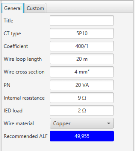
Here user should specify “CT type” and “Coefficient” of the current transformer.
Wire loop length should be calculated according to the CT connection type (4- or 6- wire connection). The difference between 4 and 6 wire schemes is depicted below.
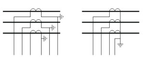
For example, if distance between the current transformer and relay is 5 meters, then in case of 6 wire connection wire loop length should be taken as 2 x 5 = 10 m and only 1,2 x 5 = 6 m for 4 wire connection. Other parameters that software need to calculate resistance of the wire is “Wire cross section” and “Wire material”. User should specify this data to represent real installation conditions of the transformer.
“PN” is nominal power of the transformer and “Internal resistance” is internal resistance of the transformer. These parameters should be taken from the transformer specifications. IED load is internal resistance of the connected relays.
Test case
We need to select current transformer for 10kV feeder. Short circuit current is 6897 A. Nominal current from load flows calculation is 345 A. According to nominal current, we will first try 600/1 ratio current transformer.
The recommended minimal accuracy limiting factor can be calculated from the formula:
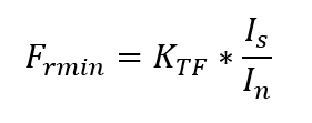
Here In is current transformer nominal current, Is is short circuit current and over – dimensioning factor. Most commonly KTF is used 1,2 – 2. For example, in our case with KTF = 2, Frmin=23.
In order to select the right rating of the current transformer, we will have to iterate for the solution by making a guess of the nominal ALF. Other information we are going to need for this calculation: wire length 20 m, cross section area 5 mm2, wire material is copper, Sn=5 VA, Rct=11 Ohm, Rload = 0,5 Ohm.
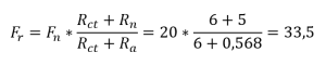
First, we will try with 5P10 current transformer.

Fr is actual accuracy limiting factor. Usually actual accuracy limiting factor is higher than nominal ALF as CT is normally under – burdened. However, from the results we see, that Fr < Frmin therefore, we should take CT with bigger nominal ALF.
In the second iteration we will take 5P20 rating and assume that other parameters are the same.
Now Fr < Frmin therefore 5P20 is good for our application.
The main drawback of this method is that user do not know what KTF value to take and what value is sufficient. For example, breaker tripping time is critical factor in selecting KTF as faster fault disconnection time will not allow CT to saturate. For this reason, it is recommended to use EA-PSM current transformer sizing function, that uses more advanced CT sizing method. Formulae for KTF is provided below:
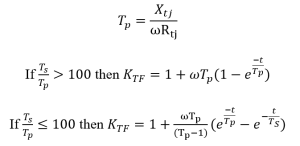
Where parameters are as follow:
Xtj – short circuit reactance;
Rtj – short circuit resistance;
w – angular frequency equal to 314 rad/s in 50 Hz networks;
Ts – CT secondary time constant that depends on magnetizing and leakage inductance as well as secondary loop resistance. In EA-PSM we assume Ts = 1s;
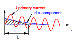
Tp – short circuit DC component time constant;
t – is time to saturation. In EA-PSM we assume that t = 0,035 s for most relays this time is enough to determine the short circuit current.
From here it is also clear that :
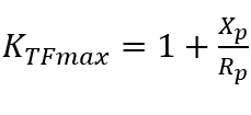
therefore it is not recommended to assume KTF value without knowing network data.
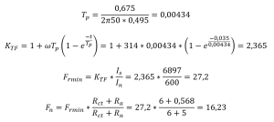
In the analyzed case:
Reference
- IEC 60044-1. Instrument transformers – Part 1: Current transformers
- Ziegler, Digital Differential Protection, Differential Protection Symposium, Belo Horizonte, 2005