Passive harmonic filters selection
Detuned filter should allow to avoid resonance conditions and absorb harmonic currents with an order higher than the tuning frequency of the reactor-capacitor arrangement.
In case of passive harmonic currents filter, high currents will flow through properly sized filter, therefore, reactor and capacitor should be selected for a sufficient current and voltage values.
Tuned filter is selected for the specific harmonic. It has low impedance for the tuned harmonic frequency, thus, acts as load on the harmonic generator. Usually more than one filter are connected to the network.
Usually, there is a need to design the filter for odd harmonic orders i.e. 5,7,11,13 and etc, the majority of these filters will be connected between phases without connection to the neutral. However, in case of unbalanced load, a third harmonic filter unit with neutral connection may be considered. Filter with higher tuned harmonic order should not be switched beforehand filter with a lower harmonic order. The rated tuning frequency of a filter unit is generally chosen slightly lower than the harmonic frequency. Thus, the impedance of the tuned filter unit is inductive at the harmonic frequency.
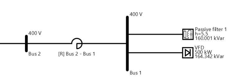
Passive harmonics filter will offer low impedance path for the tuned frequency, thus, it is possible to attract harmonics from any source connected to the power system. To avoid overload of the filter, series reactor can be connected at the input of the filter as shown in Fig. 5. This reactor will detune the filter with respect to loads connected upstream.

Fig. 5 Possible reactor connection for harmonic currents mitigation
If more than one filter are connected in parallel, the care should be taken to avoid unequal sharing of the harmonic load or parallel resonance as filter parameters will not ideally match the nominal parameters. In such cases, it is recommended to connect together the points between reactors and capacitors of each phase of the filter units for the same harmonic order which are in service.
Shunt harmonic filters reduce voltage distortion by diverting particular order harmonic current in low impedance path. In order to create low impedance path for the particular harmonic, capacitance and inductance values need to satisfy the equation (1).

where “n” is harmonic order, “f” – utility frequency in [Hz], “L” – filter coil inductance in [H], “C” – capacitance in [F]. For instance, low impedance path for the 5th harmonic can be created if multiplication of inductance and capacitance satisfy the equation (2).

EA – PSM passive harmonic filter can be defined by providing nominal voltage, target harmonic order, reactive power of the capacitors and resistance values of series RLC connection. Reactive power of the capacitors is selected according to the reactive power flows in the analyzed network. From this data, EA-PSM will automatically calculate required inductance. Filter will efficiently mitigate selected harmonic, if filter quality factor “k” is equal to 50 or higher [1]. Quality factor is used to calculate resistance values of the harmonic filter using the formula (3).

Short-circuit protection and commutation
Fuses are usually used as the short-circuit protection for the harmonic filters, however, other options are also possible, but usually are not economically feasible. The main point is that short circuit protection device should be designed for continuous current that includes harmonics. Overall current of all frequencies is shown in harmonic load flows summary table of EA-PSM.
For commutation devices, the following aspects shall be considered:
- The rated voltage of the contactor shall be equal to or higher than the maximum network voltage with the power factor correction equipment connected. Load flows calculation of EA-PSM should be done to evaluate the voltage.
- The contactor shall be designed for continuous current (including harmonics).
- The contactor shall have sufficient short time current rating to withstand peak current at the beginning of the short circuit. Peak current values are provided in short circuits summary table of EA-PSM.
References
[1] Young-Sik Cho, Hanju Cha, Single-tuned Passive Harmonic Filter Design Considering Variances of Tuning and Quality Factors, Journal of International Council on Electrical Engineering, 2014
[2] IEC 61642 Industrial a.c. networks affected by harmonic – Application of filters and shunt capacitors
Harmonics Mitigation Study:
Part 1. Single line diagram development
Part 2. Parallel and series resonance. Triple harmonics. Solutions to avoid resonances
Part 3. Passive harmonic filters selection. Short circuit protection and commutation

