It is common to use several smaller rated transformers connected in parallel instead of one bigger rated transformer in electrical power systems. The advantages of parallel operation of transformers are:
INCREASED RELIABILITY AND MAXIMIZED ELECTRICAL POWER SYSTEM AVAILABILITY.
This is because it is not necessary to disconnect the whole system if fault occurs with one of the transformers. What is more, system operators can disconnect any transformer for maintenance purpose, while other transformers will serve the load, therefore, this ensures continuous electric power supply.
MAXIMIZED ELECTRICAL POWER SYSTEM EFFICIENCY.
Sufficiently good efficiency of a power transformer is within a wide loading range, from 50% to 100% of the rated transformer power. However, if loading is smaller, efficiency of a transformer decreases, therefore, in case several transformers are installed in parallel, it is possible to switch on only those transformers which will give the total demand by running only on efficient loading.
However, in order to connect two or more power transformers in parallel, several technical conditions have to be satisfied.
SAME VOLTAGE RATIO AND IDENTICAL POSITION OF TAP CHANGER
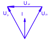
If two transformers of different voltage ratio (or tap changer position) are connected in parallel, there will be a difference in secondary voltages. Because of this, a circulating current between secondary and primary winding will appear. Internal impedance of transformer is small, therefore only a small voltage difference may cause a considerably high circulating current and additional losses. Vector diagram of two parallel transformers with different secondary voltages is depicted in Fig.1, circulating current is “I”.

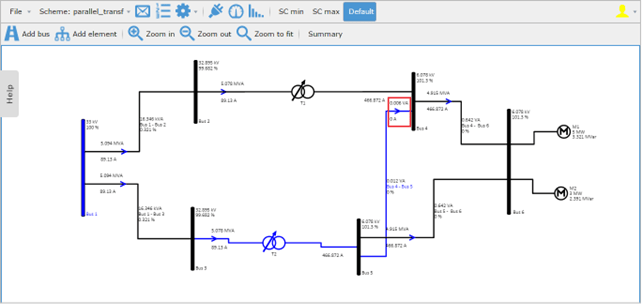
The presence of circulating current is also apparent in EA-PSM calculations. In Fig. 2 between bus 3 and bus 4 current is not flowing because system is symmetrical and both transformers have identical parameters.
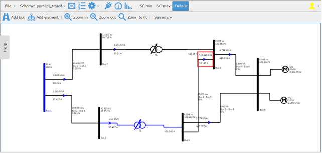
However, if we change, for example, a tap changer position in one of the transformers, the circulating current will flow between bus 3 and bus 4. This case is shown in Fig. 3 where transformer [T] Bus 2 – Bus 4 secondary winding voltage is increased by 10% and over 43 A current is present between bus 3 and bus 4.
SAME SHORT CIRCUIT VOLTAGES
Power flows carried by parallel transformers are proportional to their MVA ratings if short circuit voltages of both transformers are equal. This relationship is shown by an equation:
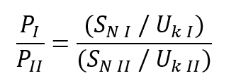
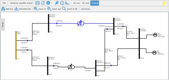
Where UkI and UkII are short circuit voltages, PI and PII power flows through transformers, SNI and SNII nominal powers (MVA) of transformers. In Fig. 4 transformer [T] Bus 1 – Bus 3 has a lower short circuit voltage, however, as both transformers have the same MVA rating, power distribution between transformers is not equal and [T] Bus 1 – Bus 3 is loaded more than[T] Bus 2 – Bus 4.
SAME PHASE SEQUENCE
The phase sequence of parallel transformers must be equal. Otherwise, during the cycle, each pair of phases will be short circuited.
SAME PHASE ANGLE SHIFT (VECTOR GROUP)
Vector group of a transformer is determined in accordance with the phase displacement between line voltages of secondary windings. If two transformers with different vector groups are connected, a circulating current occurs as shown in a vector diagram in Fig. 5, what is more, if transformers with opposite voltage vectors are connected, this will produce short circuit conditions. Therefore, only transformers with the same vector groups can be connected. In EA – PSM parallel connection of transformers with different vector groups is considered impossible.
DIFFERENT SYSTEM IMPEDANCE
It is important to notice that if impedance of parallel system branches are not equal, loop power flows will occur despite other requirements are satisfied.