Parallel resonance
Parallel resonance occurs when the system inductive reactance and capacitive reactance are equal at some frequency. In case of parallel resonance, harmonic current will oscillate between the energy storage in the inductance and the energy storage in the capacitance. It can be said that at resonance frequency, parallel connection result in a very high resistance. The oscillating current can cause high voltage distortion and the oscillating current is usually high as well. Parallel resonance principal diagram is depicted in Fig. 3.
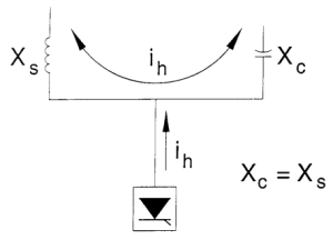
Fig. 3 Parallel resonance principal diagram
In Fig. 3 Xs is the overall system inductive reactance, combined Xc capacitive reactance of connected capacitors.
Series resonance
Series resonance is a result of the series combination of capacitor banks and line or transformer inductance. In case of series resonance, inductive and capacitive reactance compensate each other, thus creating a low-impedance path to harmonic currents. This type of resonance is used in passive filters, to provide alternative path for the specific harmonic. However, it can cause extremely high harmonic currents and failure of capacitor banks or even transformers. Series resonance circuit is provided in Fig. 4.

Fig. 4 Series resonance circuit diagram
Triple harmonics
Harmonic currents having harmonic orders that are multiples of three, are called triple harmonics (3rd, 9th, 15th etc.). These harmonics unlike others are flowing through zero sequence, thus causing high neutral conductor currents. Third harmonics are generated by 4-pulse bridge rectifiers, that are commonly used in one-phase equipment, for example, computers. EA-PSM calculates triple harmonic currents and in order to find neutral conductor current, the following formula should be used:

In a physical network with high triple harmonics, neutral current can exceed phase currents. If neutral conductor is selected inappropriately, these harmonics can cause overheating of the neutral conductor and even fire hazard. In order to avoid this, neutral conductor is sometimes selected twice the size of the phase conductor or zero sequence harmonic filters are used.
Transformer with delta or isolated star winding configuration, isolates triple harmonic currents. If there is great unbalance between the loads, triple harmonic currents can also have positive and negative sequence currents and be present in phase conductors as well.
Solutions to avoid resonances
In order to avoid resonance conditions, the main principal is to keep the resonance frequency as far away as possible from the harmonic frequencies with considerable amplitudes. The most common solution to avoid resonance problems is to connect a reactor in series with the capacitor, tuned to a series resonance frequency which is below the lowest frequency of the harmonic voltages and currents in the network.
Below the tuning frequency, the impedance of the capacitor-reactor connection is capacitive, above the tuning frequency, it is inductive. The interaction of the network inductance and the inductive impedance of the properly sized capacitor-reactor connection can no longer create a resonance condition.
Tuning order can be calculated using equation

In most networks, the 5th harmonic is the lowest frequency with a considerable amplitude. For such networks, it is useful to choose a capacitor-reactor connection with a tuning frequency below 5. However, if the network is loaded with strong 3rd harmonic voltages, the tuning frequency shall be below 3.
To properly size reactor, calculations should be done at each possible capacitor bank step.
References
[1] Young-Sik Cho, Hanju Cha, Single-tuned Passive Harmonic Filter Design Considering Variances of Tuning and Quality Factors, Journal of International Council on Electrical Engineering, 2014
[2] IEC 61642 Industrial a.c. networks affected by harmonic – Application of filters and shunt capacitors
Harmonics Mitigation Study:
Part 1. Single line diagram development
Part 2. Parallel and series resonance. Triple harmonics. Solutions to avoid resonances
Part 3. Passive harmonic filters selection. Short circuit protection and commutation